Direct Dielectric Cooling for Power Converters
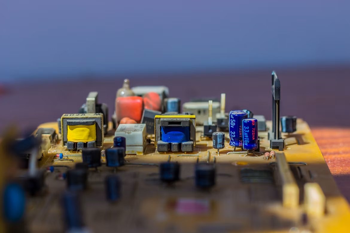

Power devices enable converters to operate at a higher power density and reduce switching losses and the size of passive components, but the remaining losses are concentrated into a smaller volume. Thermal management can become a limiting factor even when the converter is more efficient than an equivalent, silicon-based design.
Direct dielectric cooling offers a way to manage this heat. Instead of keeping the coolant separate from energized hardware, an electrically insulating liquid can be used in closer proximity to the power stage. This opens cooling approaches that are difficult to achieve with conventional, water-glycol cold plates.
But once coolant is in direct contact with the electrical system, it becomes part of the converter’s packaging and insulation environment. Thermal performance must be considered together with electrical insulation, fluid behavior, material compatibility, and long-term reliability.

Shorten the thermal path
In a liquid-cooled power module, the heat moves from the semiconductor junction through the die attach, copper metallization, ceramic substrate, baseplate or heat spreader, thermal interface material, and cold plate before it reaches the coolant.
Each layer adds thermal resistance. Silicon carbide (SiC) and gallium nitride (GaN) power converters are becoming smaller and more power-dense, reducing junction-to-coolant resistance. Direct dielectric cooling can bypass some of these layers.
Because the liquid is electrically insulating, it can contact energized copper or other parts of the power stage. Depending on the design, the fluid can flow across exposed metallization, through narrow passages close to the devices, or through jets targeted at the hottest surfaces.

This does not require the inverter to sit inside a large tank. The entire PCB may be immersed, only the power stage may sit inside a flooded cavity, or the liquid may circulate through sealed channels inside the module. The cooling system can be designed around the areas where heat is generated.
The main opportunity is to redesign the package around the coolant. Simply immersing a conventional module still leaves much of the original thermal path in place. More thermal resistance can be removed if layers such as the ceramic substrate, baseplate, thermal interface material, or cold plate are reduced or eliminated.
Single-phase or two-phase?
Direct dielectric cooling can use either a single-phase or two-phase approach.
In single-phase cooling, the liquid stays in its liquid state while it absorbs heat. The coolant may move through natural convection, but higher-performance systems pump it through channels or direct it toward hot surfaces.
Cooling performance depends on the fluid’s thermal conductivity, heat capacity, viscosity, flow rate, and geometry of the flow path. Higher flow can improve heat removal but also increase pressure drop and pumping power.
On the other hand, two-phase cooling uses boiling. Once the hot surface reaches the fluid’s saturation temperature, vapor bubbles begin to form and carry heat away through phase change.
The vapor moves to a condenser, where it turns back into liquid and returns to the heated area. Because boiling uses latent heat, it can remove large amounts of heat while keeping the surface temperature close to the fluid’s boiling temperature.

The tradeoff is that boiling adds more variables to the cooling system. System pressure affects the boiling temperature, and the condenser must remove the heat carried by the vapor. Engineers must also avoid critical heat flux. If vapor generation becomes too intense, parts of the hot surface no longer stay covered by liquid.
The better option depends on the application. Single-phase systems are easier to control and model because there is no boiling, vapor management, or critical heat-flux limit. However, they do need enough liquid flow to carry the heat away.
For a two-phase system, higher local heat flux can be handled with less dependence on pumping. The tradeoff is added complexity. The system needs a condenser, pressure control, and reliable paths for vapor to leave the hot surface and liquid to return.
The choice can be made based on the heat flux, size, operating conditions, and acceptable system complexity of the converter.
Coolant becomes part of the design
Once dielectric fluid surrounds energized SiC or GaN hardware, it becomes part of the insulation system, and properties such as dielectric strength, permittivity, and conductivity begin to affect the electrical behavior of the converter. These properties can also change with temperature, moisture, contamination, and aging.
This is important in high-voltage converters because a high dielectric-strength rating does not mean designers can simply reduce the spacing between busbars or PCB conductors. Local geometry is still crucial to understand because sharp copper edges, small gaps, and the points at which metal, solid insulation, and liquid meet can produce high electric-field stress.
Two-phase cooling adds another complication because the liquid is allowed to boil. The vapor bubbles that form have different electrical properties from the surrounding liquid. When they move through the converter, they can change the local electric field.
A recent research paper found that stronger boiling reduced partial discharge inception voltage in the tested dielectric fluid. The result cannot be applied to every two-phase system, but it shows that a surface optimized for boiling also needs to be checked for insulation performance.
Material compatibility can also become a long-term problem. The fluid may remain in contact for years with PCB laminates, solder masks, coatings, adhesives, seals, plastics, and other materials. Some fluid material combinations can cause swelling, shrinkage, leaching, or delamination over time. The coolant can also degrade or become contaminated, which may change both its thermal and electrical properties.
Direct dielectric cooling can simplify parts of the thermal package while making cooling and insulation more connected. Fluid selection depends on how effectively the liquid removes heat, how it behaves around high-voltage conductors, and how the immersed materials respond over time.
Electrically insulating coolant
The main advantage of direct dielectric cooling for power electronics is that an electrically insulating coolant can be brought much closer to the semiconductor and other hot components. This shortens the thermal path and gives designers more freedom to rethink substrates, interfaces, and other parts of the package.
The post Direct Dielectric Cooling for Power Converters appeared first on Power Electronics News.